Why CAN exists
Vehicles did not become electronically complex all at once. They accumulated electronic functions one subsystem at a time: engine management, anti-lock braking, airbags, body controls, electric steering, battery management, diagnostics, infotainment, and more. If every electronic control unit, or ECU, needed a dedicated point-to-point wire to every other ECU, the harness would become too heavy, too expensive, and too hard to maintain.
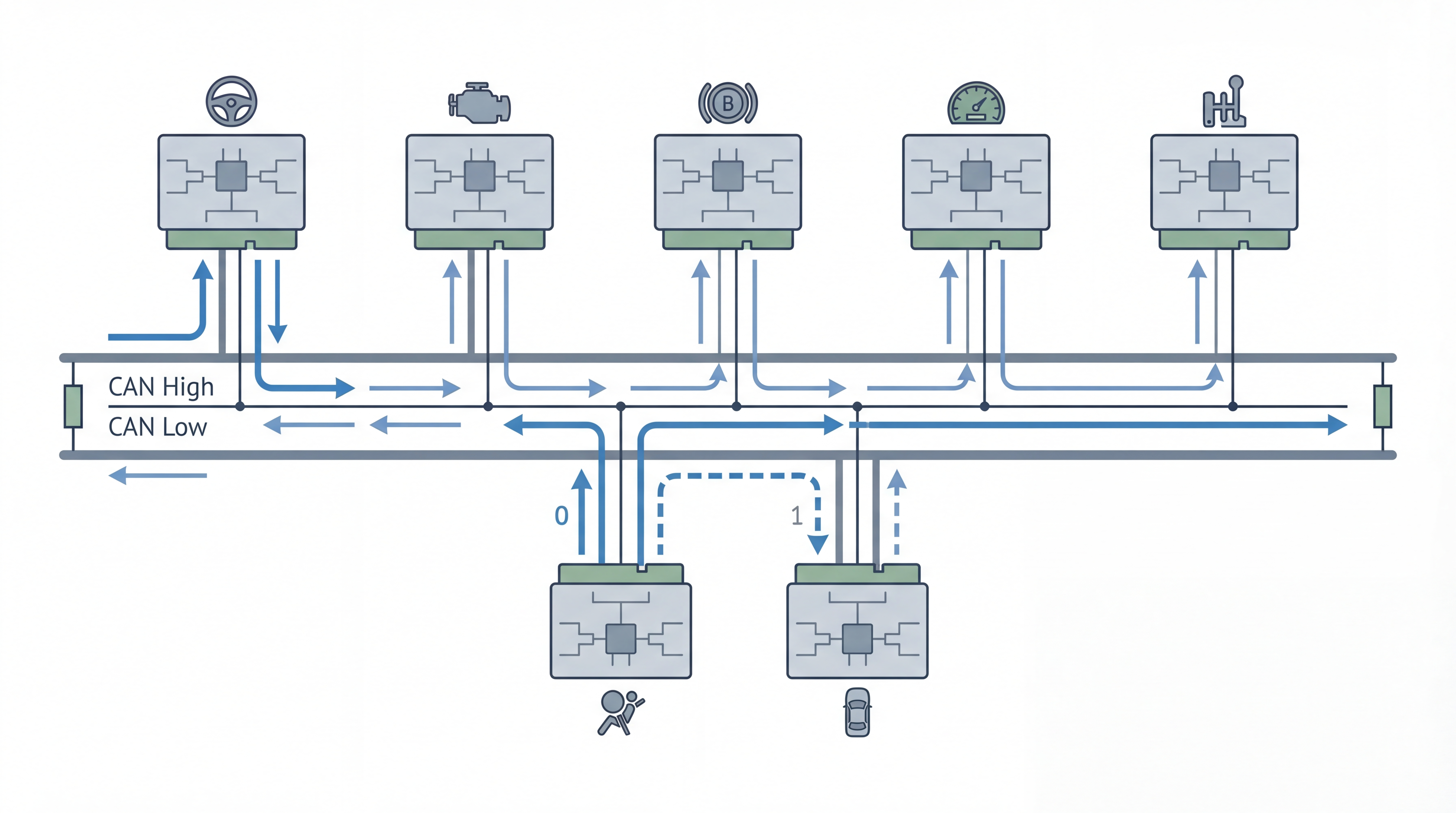
CAN, short for Controller Area Network, solved that problem by letting many nodes share the same bus. Instead of each ECU owning a private wire to every destination, all nodes connect to a common communication medium and decide whether a message matters by looking at the message identifier. That shift reduced harness complexity and made distributed control practical.
Bosch introduced CAN to make real-time control communication more robust in automotive environments. The design goal was not raw bandwidth. It was dependable message exchange in noisy electrical conditions, with multiple controllers competing for access without a central master.
The mental model: CAN is message-oriented, not address-oriented
Classic network newcomers often assume a CAN frame behaves like an Ethernet packet sent from device A to device B. That is not the best mental model. CAN is fundamentally message-oriented:
- A frame carries an identifier that represents the meaning and priority of the data.
- Every node on the bus sees the frame.
- Each ECU decides locally whether it should process that identifier.
- The bus does not need a centralized traffic coordinator.
That means one wheel-speed frame can be consumed by the ABS ECU, the stability-control ECU, the instrument cluster, and the gateway at the same time. The sender does not need four separate transmissions.
How nodes share one wire pair without chaos
The most famous CAN behavior is non-destructive arbitration. When two or more nodes begin transmitting at the same time, they do not simply collide and retry randomly. They compare what they send with what they read back from the bus.
In CAN signaling, a dominant bit overrides a recessive bit. During arbitration:
- Each sender starts transmitting its identifier.
- Every sender monitors the bus while transmitting.
- If a node sends recessive but reads dominant, it knows a higher-priority frame is present.
- That node immediately stops transmitting and becomes a receiver.
- The highest-priority identifier continues without corruption.
This is why CAN is so attractive for control traffic. High-priority signals, such as brake or powertrain information, can win access without a software scheduler negotiating every exchange.
What is inside a classical CAN frame
A classical CAN data frame is compact, but every field exists for a reason:
| Field | Purpose |
|---|---|
| Start of frame | Marks the beginning of a transmission |
| Arbitration field | Contains the identifier and determines priority |
| Control field | Includes details such as payload length |
| Data field | Carries up to 8 bytes in classical CAN |
| CRC field | Checks frame integrity |
| ACK field | Lets receivers confirm successful reception |
| End of frame | Terminates the frame cleanly |
Two identifier lengths are common:
- 11-bit identifiers for standard format
- 29-bit identifiers for extended format
The identifier is not just a label. It also controls bus priority, because numerically lower identifiers win arbitration.
Why classical CAN felt so well matched to ECUs
For many ECU tasks, the payload itself is small. A throttle request, torque limit, wheel speed, or door status is usually only a few bytes. That made CAN an efficient fit:
- The data size matched the control problem.
- Many producers and consumers could share the same message.
- The bus stayed useful even with modest microcontrollers.
- The physical layer was robust enough for harsh automotive environments.
The result is that CAN became the workhorse network for distributed control, diagnostics transport, and vehicle coordination long before cars started carrying camera and radar data at scale.
CAN is designed to notice faults and contain them
Another reason CAN endured is its fault behavior. The protocol does not just detect errors. It also tries to prevent a bad node from taking down the entire network indefinitely.
Kvaser summarizes five major error detection mechanisms in CAN:
- Bit monitoring
- Bit stuffing checks
- Frame checks
- Acknowledgement checks
- Cyclic redundancy checks
CAN nodes also maintain error counters. As faults accumulate, a node can transition through more restrictive states:
- Error active: normal participation
- Error passive: reduced ability to disturb traffic
- Bus off: the node removes itself from active communication
This is called error confinement. It is one of the protocol features that makes CAN feel much more engineered for control systems than a casual serial bus.
Where DBC files fit into the picture
A raw CAN frame is only the transport container. Engineers still need to know how to interpret the bits inside each payload. That is where DBC files come in.
A DBC file describes:
- Message identifiers
- Message names
- Signal names
- Bit positions and lengths
- Scaling and offsets
- Units
- Comments and metadata
Without that database layer, raw CAN traffic is just hexadecimal payloads. With it, an engineering tool can turn bytes into values like engine speed, battery voltage, steering angle, or gear position. This is exactly why a focused DBC editor matters in day-to-day automotive work: the communication bus is only half the problem, and message interpretation is the other half.
CAN does have limits
Classic CAN is not universal. It was optimized for dependable control messaging, not everything a modern vehicle might want to move over a network.
Its main limits are:
- Payload size is capped at 8 bytes per frame.
- Classical CAN data rate is generally limited to 1 Mbit/s.
- Rising sensor, logging, and software-update demands can exceed that comfortably.
- Shared-bus traffic engineering becomes harder as message count grows.
Those limits are exactly why CAN FD, Automotive Ethernet, and more centralized vehicle architectures became more important over time. But the existence of newer buses does not erase why CAN remains everywhere: it solves a large class of control problems elegantly.
Working with CAN databases in practice
In real projects, CAN protocol understanding must be paired with clean DBC maintenance. As message sets grow, review quality around signal mapping, scale, and ownership becomes as important as bus behavior itself. A focused DBC workflow can reduce avoidable decode and integration mistakes.
Product pages:
The shortest honest summary
CAN is not the fastest in-vehicle network, and it was never meant to be. It became dominant because it gives distributed ECUs a practical way to communicate with predictable priority, modest wiring, and strong fault behavior. In vehicle engineering, that combination is often more valuable than raw headline bandwidth.